6/17/2014

Creating a Surface From Scratch

A minimal surface
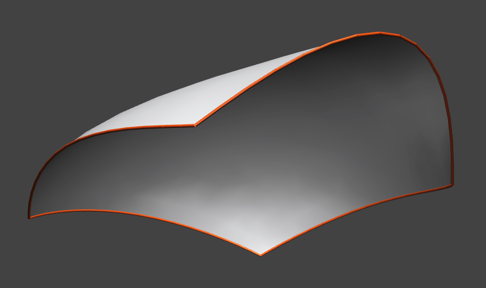
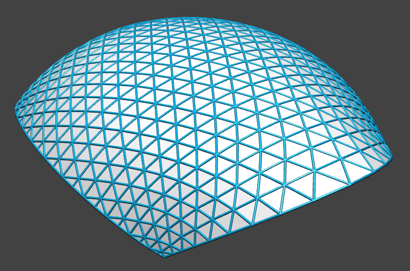
In this post, we describe how VaryLab can be used to create a minimal surface from scratch. We use the build-in primitives of VaryLab to create a start geometry and modify this using interactive editing as well as tabular data input. Subdivision steps are used to obtain finer resolutions and to create the final mesh. This mesh is then optimized to have the shortest edge lengths possible with certain boundary conditions. This gives a coarse approximation of the shape of a minimal surface with the given boundary.

Creating a start geometry

The quad mesh generator dialog
We start by creating a simple square with a generator from the menu Generators->Quad Mesh. Set the u and v resolution to 2 and uncheck the "Use Dimonds" box. This creates our start geometry, a quadrilateral. You can move the vertices in space by selecting and Shift-Mouse-Drag
Initial quad-surface


An alternative way of coordinate input is the data table in the data visualization panel. You can activate the coordinate table by selecting the VPosition data channel and choose a table visualization for vertices. The table shows the coordinates of either all or just the selected vertices.

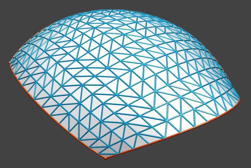
Linear subdivision surface
To obtain a finer surface resolution, we use several subdivision steps. From the menu choose Subdivision->CatmullClark. Here we can adjust subdivision parameters to create a linear subdivision and fixed boundary interpolation.

Coordinates can be edited in the data visualization panel

Adjust the position of vertices that should remain in a fixed location and keep them selected. The optimization can fix selected vertices in all or just some dimensions.


Optimization

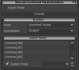
Optimization user interface
The optimization core of VaryLab can be used to shorten the edge lengths of the mesh and keep certain vertices at fixed positions. The corresponding energy is the spring energy. Activate the Sping Energy optimizer from the Optimizer Plug-ins panel. The spring length should be set to constantly 0. In the Optimization panel you can select constraints. We fix all selected vertices. All other boundary vertices can move along the z-direction. To achieve this effect, check all boxes of the selection constraints and the x and the y check boxes of the boundary constraints.

To start the optimization you can either choose to interactively optimize by pressing the Animate button. Or you can optimize the mesh for a predefined number of steps with the Optimize button.
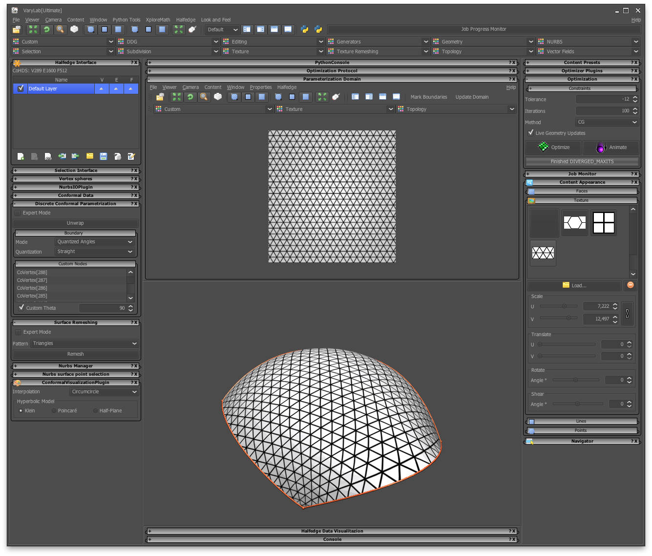
6/16/2014

Remeshing with Boundary Conditions

Initial Surface
A boundary of a discrete surface is usually a closed polygonal curve in space. If a surface has multiple boundary components, one speaks of a multiply-connected surface. In this article we deal with surfaces that have one boundary component. We call those simply-connected or surface with disk topology.

Source unstructured triangle mesh
Starting with a discrete surface with one boundary component we want to create a mesh where the pattern of the mesh aligns with the boundary curve in a nice way. You can download the example model here. We use a triangle pattern and demonstrate the usage of automatic as well as custom alignment of the boundary.

Boundary aligned parameterization

Custom boundary condtions
In order to create a new mesh from an existing surface, we first need to create a suitable parameterization for the input data. For general information about parameterization have a look into the Discrete Surface Parameterization article. In our case we want to create a parameterization that respects the geometry of a regular triangle pattern which means boundary angles of the domain of parameterization should be quantized to a multiple of 30º.

For the given triangulated surface, we create a map from the surface to a rectangle. In order to specify these boundary conditions, you select the four corner vertices of the mesh and type in the desired boundary angle in the "Custom Nodes" fold-out panel inside the "Discrete Conformal Parameterization" panel. If the vertices do not appear, press the Unwrap button and select the vertices again. To create the rectangle, the four vertices must have a custom angle of 90º. The general boundary setting should be set to "Quatized Angles" for the mode, and "Straight" for quantization. These settings affect all unselected vertices. If you press the unwrap button the mapping is calculated and can be previewed using the texture display features of VaryLab.

The VaryLab main window during parameterization. In 
the parameterization domain panel (top) you see can review the 
current domain. A texture is selected from the appearance panel
to preview the mapping.

Aligned Remeshing


Remeshing with boundary aligned
triangles
If we have a mesh with sufficiently quantized boundary angles, we can go on and create a boundary aligned mesh from this data. In our case we have four angles of 90º and at all other vertices the boundary of the domain is a straight line which corresponds to a boundary angle of 180º.

The remeshing user interface
To perform the remeshing step select the "Boundary aligned Triangles" pattern from the "Surface Remeshing" panel and hit the "Remesh" button. You can download the result mesh here.